Below is the (ongoing) resultant data
including pictures of the setup and description of the implementation.
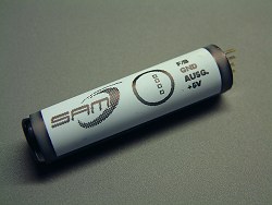
The
design uses an SCL field sensor type FGM-3 (From Fat Quarters
Software). The signal from this unit is fed into the integrated circuit
which performs all the functions required to the level of providing a
digital output on eight parallel lines which mirrors the tiny field
fluctuations. This output is then fed directly to the input
port of a serial-to-ether server which forwards the data over wired
(CAT-5) Ethernet to a computer for data analysis.
To remotely deploy this sensor,
I am using the SITE Player Telnet Serial-to-Ether
converter/controller from Netmedia.com
The Sensor (FGM-3) is housed inside a small
section of 4" PVC tube that is capped on both ends with PVC
ends.
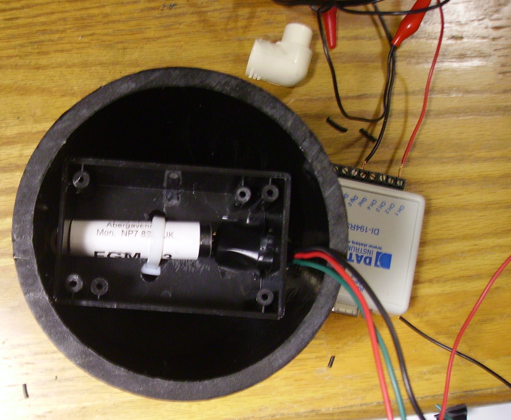
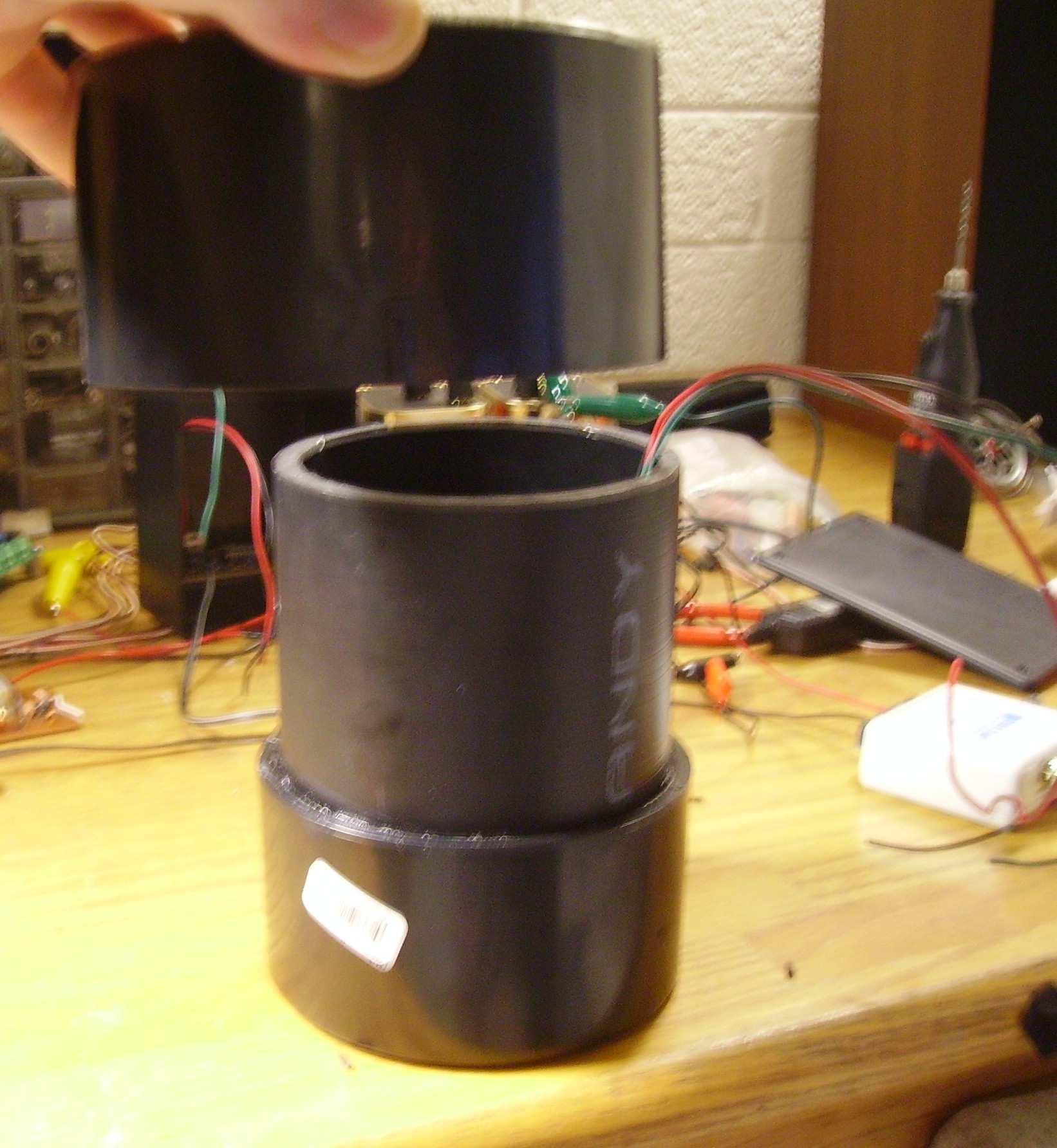
Here is the container with the PVC Cap About
to be placed onto it.. note the wires exfiltrate the container thru a
small hole drilled in the top of the upper PVC Cap.... the wires are
sealed on both sides with a rubber grommet and silicon sealant to
ensure the inside of the container remains Waterproof.
In the future, I hope to employ the Zigbee
type "Xbee" wireless network transceiver set so I can get rid of the
Cat-5 cable (if the price of the zigbee technology comes down abit).
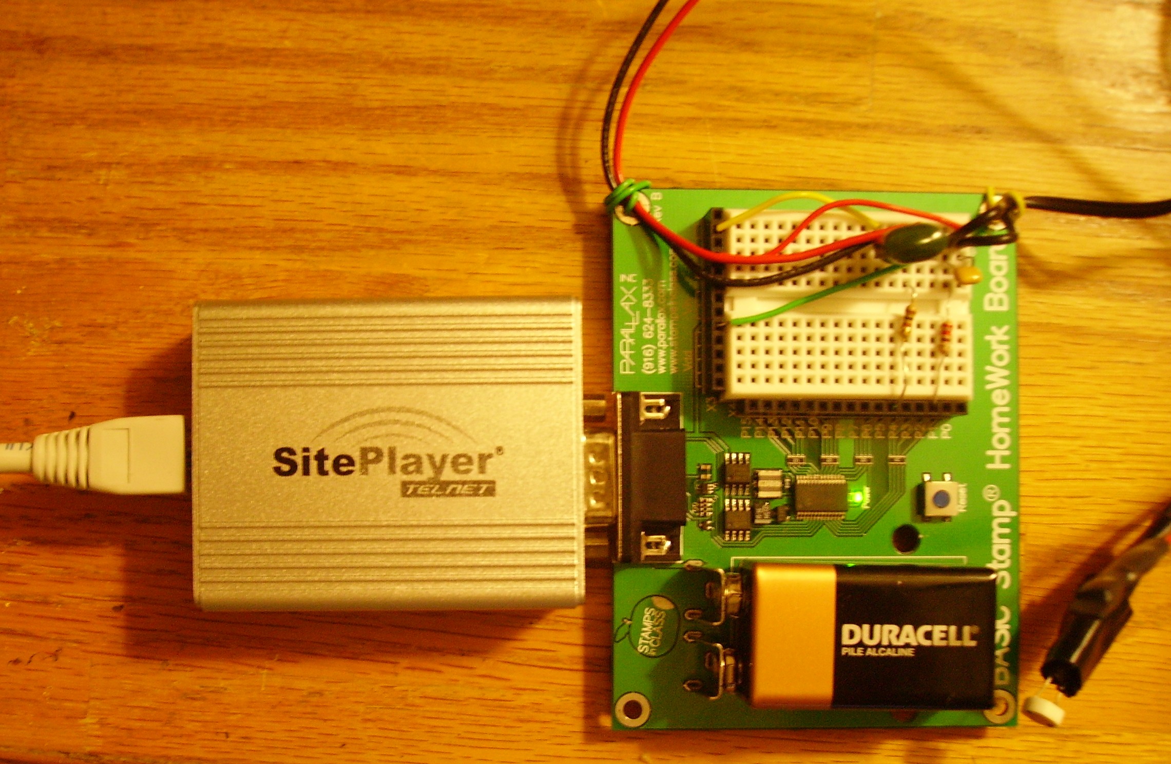
Here is a picture of the Temperature/Light
Sensor Suite and it's connection to the SitePlayer which converts the
Serial output from the Basic Stamp to ethernet for the run over CAT5
cable into our Lab. A second SitePlayer Converts the Data back into
serial as it is fed into the logging computer's Serial port.
The use of SitePlayer enables the use of (available) long data runs
using them as serial to ethernet bridges. Notice the Temperatureand
light sensors are extended 20" on wires from the basic
stamp and the basic stamp's power supply is provided by a 9V adapter
piggy backed off the site-player's power supply (not a 9v battery) near
the sensor array.
Temperature and
Light Readings are taken at the same time as the magnetic readings
enabling analysis of the magnetic data to be correlated with
the Temperature
and light intensity readings.
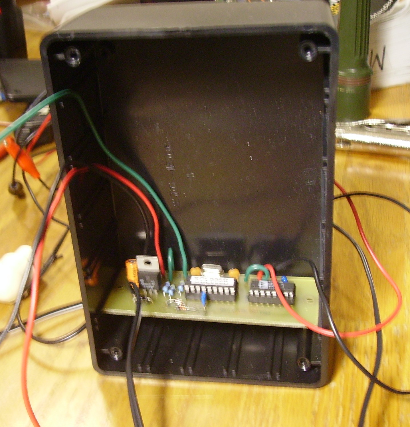
The PC Board (Below) is connected to the
FGM-3 Sensor and enables users to specify 1 of 4 sensativity levels
(switch) as well as a sensor reset button which I've noticed comes in
quite handy. The Board is mounted into a standard Plastic Enclosure
that is near a "Wall Wart" Double Regulated Powersupply.
The Sensor's Rectangular Signal is
fed into the PC Board which performs all the
functions required to the level of providing a digital output on eight
parallel lines which mirrors the tiny field fluctuations.
This output can be fed directly to the input
port of a computer... the PCB's IC converts the period
variations to an eight bit digital
output, (after amplification and comparison to a
chosen zero reference).
The sensors will be buried
underground 14" below the surface of my back yard to help stabilize the
units Temperature as
variances in the FGM-3 Sensor's operational Temperature
will cause the readings to change. Therefore a Temperature/Light:Magnetic
Flux reading correlation must be implemented.
Much More Pictures/data to come!

